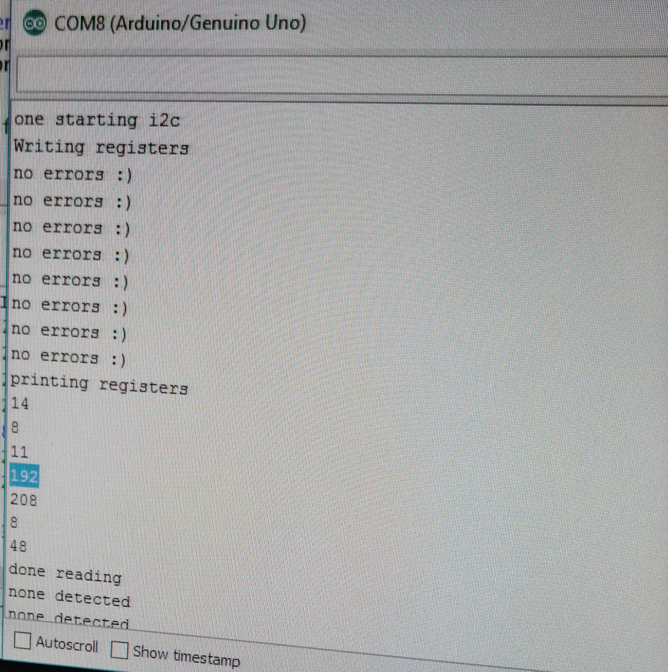
Fig.1: Camera Register Output
The objective of this lab was to use a camera hooked up to an FPGA to read in data from the camera and display it on a screen, eventually analyzing the image for both color and shape to detect targets during competition
The first thing we did was get the Arduinos programmed to write registers to the camera. To do this we read through the
camera datasheet and found the right registers to set the data structure (RGB444), resolution (176x144), camera noise, using an
external clock, pixel format and more. We had difficulty with getting the right results from our camera and the problem proofed to be
from the registers we had set using outdated data sheet. Eventually, we were able to get the correct registers and a snippet of our
code is shown below.
      	Serial.println("Writing registers");
    	Serial.println (OV7670_write_register(0x12, 0x80)); //COM7: Reset registers, enable color bar, resolution and pixel format
    	delay(100);
    	Serial.println(OV7670_write_register(0x12, 0x0E)); //COM7: Reset registers, enable color bar, resolution and pixel format
    	Serial.println(OV7670_write_register(0x0C, 0x08)); //COM3: Enable scaling
    	Serial.println(OV7670_write_register(0x14, 0x0B)); //COM9: To make the image less noisy
    	Serial.println(OV7670_write_register(0x11, 0xC0)); //CLKRC: Use external clock directly
    	Serial.println(OV7670_write_register(0x40, 0xD0)); //COM15: pixel format
    	Serial.println(OV7670_write_register(0x42, 0x08)); //COM17: DSP color bar enable (0x42, 0x08)
   	Serial.println(OV7670_write_register(0x1E, 0x30)); //MVFP: Vertically flip image enable
    	Serial.println(OV7670_write_register(0x8C, 0x02)); //enable RGB444
To run the Arduino program, we needed to protect the camera. We had to disable the internal pull-up resistors that are a part of
the Arduino’s I2C interface. This is because they pull the signals that set up our camera to 5V, while our camera requires 3.3V.
Sending 5V through will harm the camera. We did this by locating the twi.c file at C:\Program Files (x86)\Arduino\hardware\arduino\avr\libraries\Wire\src\utility.
Then we commented out the following lines of code:
       //activate internal pullups for twi
       digitalWrite(SDA,1);
       digitalWrite(SCL,1);
We read the camera data and the picture below shows the output. Comparing the output to the written values into the registers, we confirmed that our camera was working
correctly and is ready to send data into the DE0-Nano FPGA.
Fig.1: Camera Register Output
We tested our M9K block code which communicated with our VGA driver to output the colors which will be received from the camera. We wrote a few hard coded colors to be displayed on the monitor.
The following example shows how it is done
	    if(VGA_PIXEL_X>44 &&VGA_PIXEL_X<=66 &&VGA_PIXEL_Y<(`SCREEN_HEIGHT-1))begin
		pixel_data_RGB332 = 8'b11111100;  //set color
		W_EN = 1'b1;   //write enable
	    end
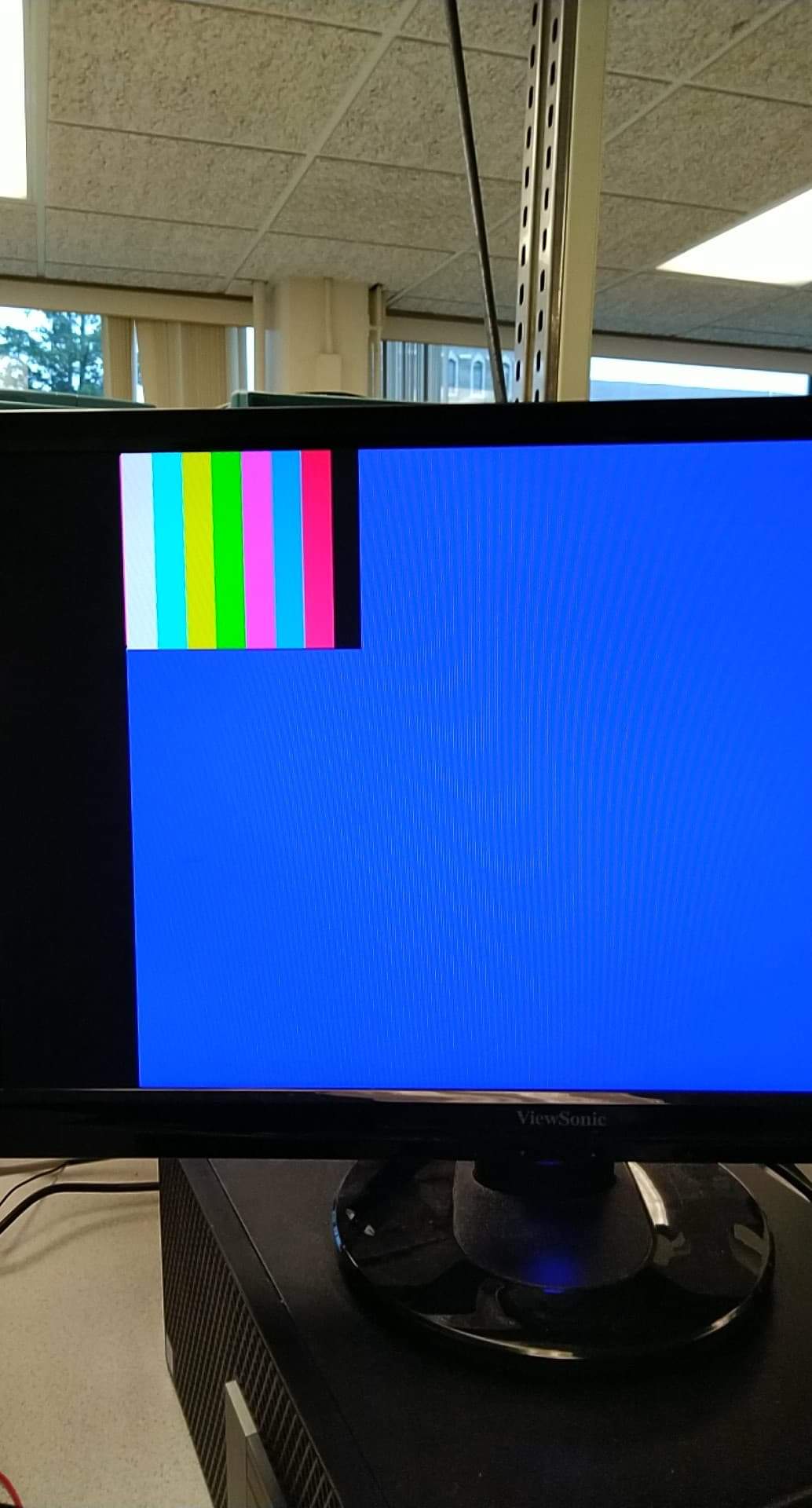
Fig.2: Color pattern output
Our camera outputs a data structure of RGB444 in 16 bits. We however need only 8 bits out of the 16 bits in order to save on memory. The Downsampling code collects all the data from the camera and selects only the most important bits necessary to display the colors we need. The OV7670 Camera can only output 8 bits of a pixel at a time through D7 - D0 (output connections). Using the camera clock cycle (see fig.3), we sampled down the output into RGB332.
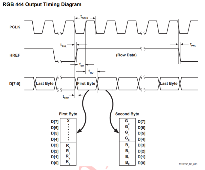
Fig.3: Clock cycle from the OV7670 Datasheet.This shows how the output from the clock is received based on time cycle
      //This set of codes receive camera data in RGB444 and downsamples it into RGB 332 by taking the important bits
      if (CAM_HREF_NEG) begin   //href clock is high
      	if (newByte == 1'b0) begin
				temp[7:0] = data;
				W_EN      = 1'b0;
				X_ADDR    = X_ADDR;
				newByte   = 1'b1;
				pixel_data_RGB332[4:0] = {data[7:5], data[3:2]};//get values for blue and green
			end
			else begin
				pixel_data_RGB332[7:5] = {data[3:1]};// get value for red
				X_ADDR = X_ADDR + 10'b1;
				W_EN = 1'b1;
				newByte = 1'b0;
			end
	end
In order to know what color our camera is seeing without using the VGA driver to output to screen, we need to read the pixels that come from the camera. We did so by implementing another code in our downsamplier to make the colors vivid. below is a diagram showing the logic behind the implementation. We used threshold values to make sure that our colors are truly present.
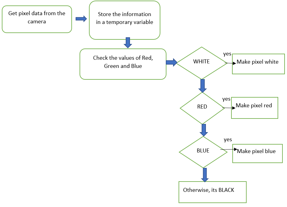
Fig.4: Making our colors look right