Fig.1: Image taken from 3400 website
The goal of this lab was to start testing different signal processing, both audio and optical. The audio team worked on processing certain frequencies and ignoring background noise like talking and music whereas the optical team worked on detecting other robots' IR emitters and ignoring the decoy frequencies.
Note: For both of our implementations, we had little chance making our amplifier circuits to work. We therefore resorted to Team Alpha's approach.
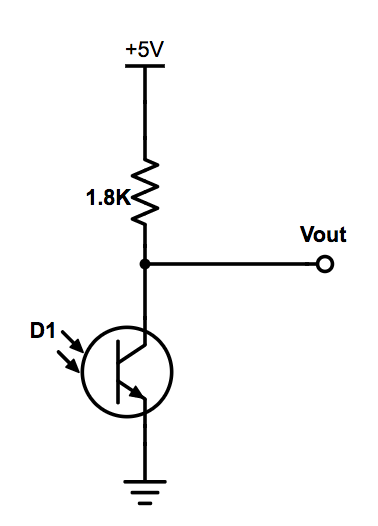
First, the optical team attempted to detect IR emitters on "hats" given to us by the TAs. The emit IR light at 6kHz, which is not visible to humans but can be read by our IR sensor (OP598). The IR sensor was hooked up as seen below.
Fig.1: Image taken from 3400 website
We used the Arduino library Open Music Labs’ FFT to analyze all the input from the sensor, and tried to detect a peak at the desired frequency. First we made sure we could see the peak on the oscilloscope, as seen below.
Next we implemented an amplifying circuit based on Team Alpha's solution from last year as recommended by the TAs after we could not get our personally designed op-amp circuit working.We used a similar circuit to the one below except we used a photo transistor in place of the microphone.
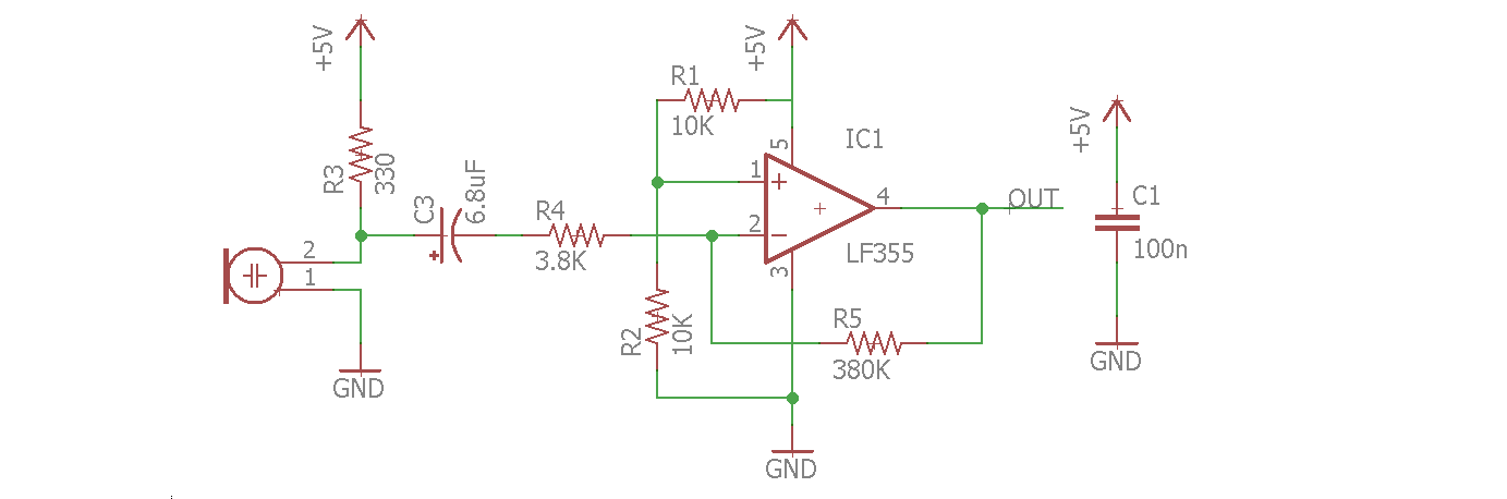
Fig.2: Image taken from Team Alpha's Website
After this we returned to the FFT library, where we were successfully able to identify the 6kHz bucket in the 42nd group, which the decoy hat had no affect on due to the spacing of the buckets. Below you can see our FFT analysis, where the 42nd bucket is clearly high in the presense of the hat and low without it.
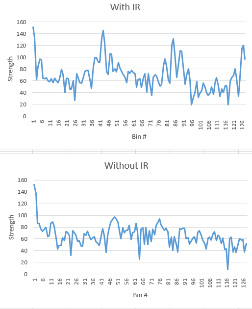
Fig.3: FFT of IR sensor
Therefore, the visual task was complete. See below for a video of Gary responding to the robot hat and not to the decoy!
We began with the circuit provided for the lab (see fig. 4) but realised that we needed to amplify our waveforms because they had been attenuated(see fig. 5). We began the task independently trying to build a circuit to detect our 660Hz sound wave. We worked hard switching between numerous designs of band-pass filters to amplifiers but nothing seemed to work for us. We decided to resort to Team Alpha's approach. We used the circuit from fig. 2 above. with slightly different values for the components. Our results, however, were very similar to Team Alpha's.
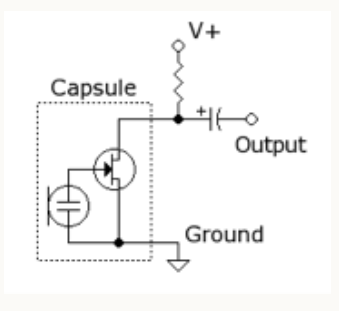
Fig. 4: Initial circuit built to test microphone. Image taken from 3400 website's Lab 2 instructions.
We run our circuit using the example fft arduino code (fft_adc_serial). We plotted our values on Excel.
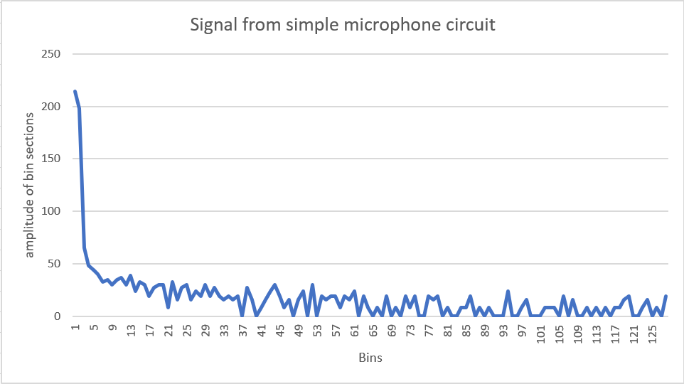
Fig. 5:Image of FFT of signal.
After adding the amplification, this was what we observed. We were able to locate our frequency in bin #5.
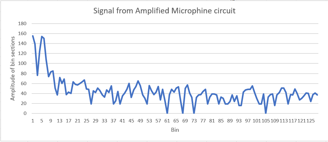
Fig. 6:Amplified version of fig. 5. 660Hz frequency is located in bin 5.
We used the oscilloscope to varify that the circuit was really working and the video below shows that when the 660Hz signal was played, the marked signal rises.
We therefore made some specification to our code to sense when the wave in bin #5 was the highest. This was how we could tell when an incoming frequency was 660Hz. The video below shows a test performed on the detection of 660Hz.
We combined the two functions. To implement them together, we modified our arduino code. Inside the loop, we alternated between the two functions we created. This allowed both sound and IR sensing to work together. Below is a snippet of our code with the modifications.
    void loop() {
     while(1) { // reduces jitter
      fft_audio ();
      fft_visual();
     }
    }

    void fft_audio() {
     ...//code here
    }

    void fft_visual() {
    ... //code here
    }
The video below is the demonstration of the two functions working together. The green light is for sound and the red light is for IR sensing.