The goal of this lab was to familiarize ourselves with the Arduino Uno, the Arduino IDE, and the github repository. To do this, we created programs that tested the functionality of our arduino using LEDs and Parallax servos. After testing our arduino, we assembled our robot and ran a simple code on it.
To begin the lab, we opened up the blink sketch and examined it to understand how it works. We successfully blinked the internal LED with the following code:
        void setup() {
          pinMode(LED_BUILTIN, OUTPUT);  //This initializes the LED_BUILTIN as an output
        }

        void loop() {
          digitalWrite(LED_BUILTIN, HIGH);  //Turns the LED on
          delay(1000);  //Leaves the LED on for one second
          digitalWrite(LED_BUILTIN, LOW);  //Turns the LED off
          delay(1000);  //Leaves the LED off for one second
        }
The video below shows the blinking built-in LED on the arduino motherboard.
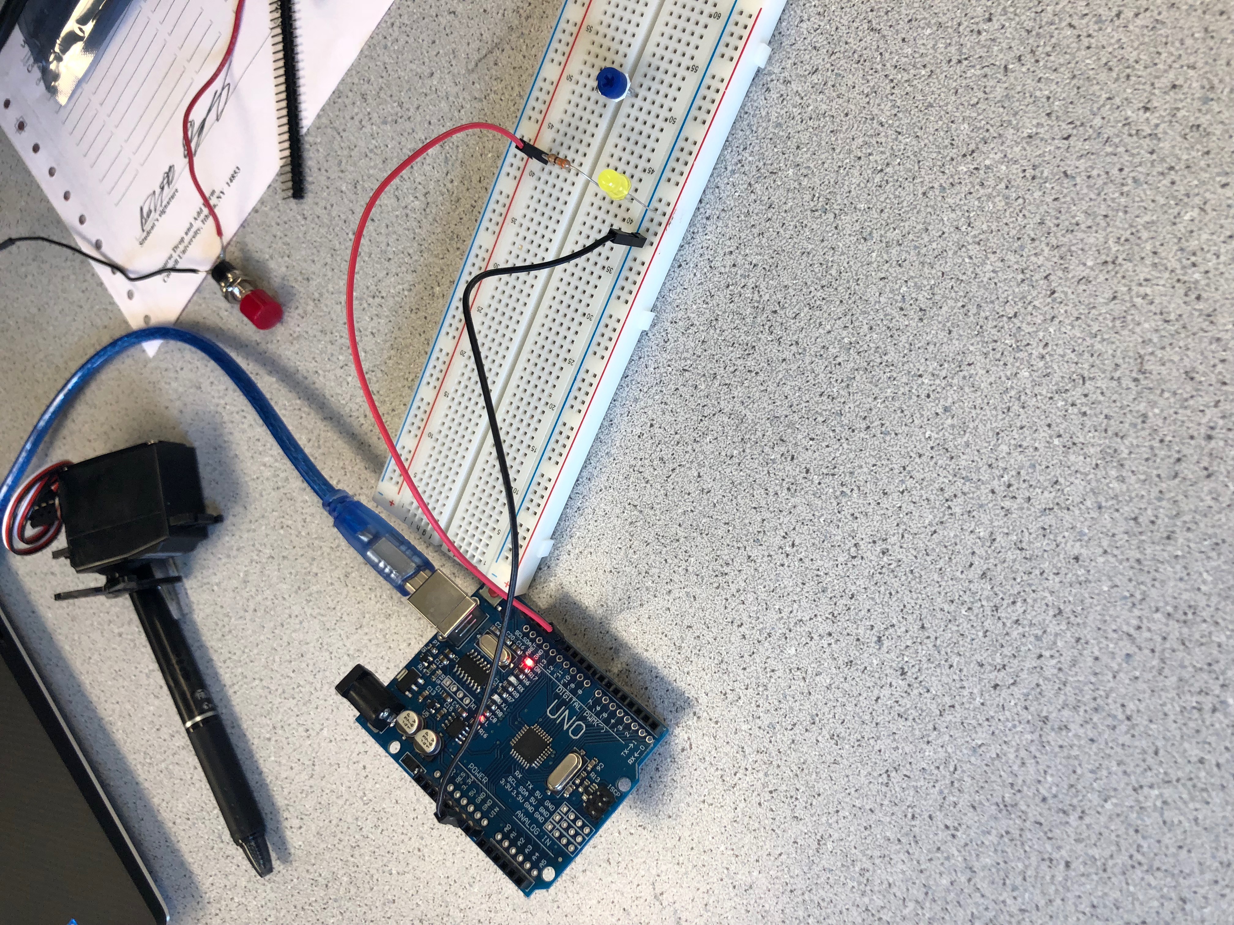
Next, we replaced the internal LED (LED_BUILTIN) with an external LED by mapping the output to a pin 6. A picture of that can be seen below: we simply connected the LED to the Arduino's ground port and the LED's power pin to an IO pin, and changed the code to replace LED_BUILTIN with pin 6.
Watch video below to see how it works.
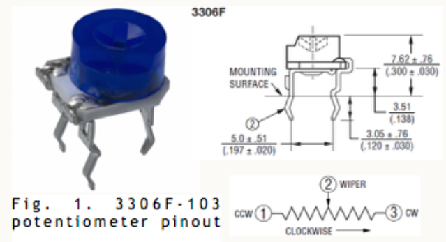
Potentiometer contains resistors so it can be used as a voltage divider which we did in this lab. We connected only two of the pins of the potentiometer including the wiper and put it is series with another resistor to serve as a known resistance value. Then we collected the voltage values through the potentiometer as we varied its resistance.
We used our code and potentiometer to vary the brightness of an LED. We used a pulse-width modulator (PWM)to scale the potentiometer values, which enabled us to change the brightness of the LED. Essentially, the duty cycle of the output corresponds to time on for the LED, and because the time on and off is much faster than we can process, it appears to be a less bright LED when the duty cycle is lower and vice versa.
Below is our brightness varying code.
      int pin=3;

      void setup() {
      pinMode(A0, INPUT);
      Serial.begin(9600);
      pinMode(6, OUTPUT);
      }
      void loop() {
      int value=analogRead(A0)/5.7;
      Serial.println(value);
      delay(20);
      analogWrite(6,value);
      }
Watch this short video to observe the results
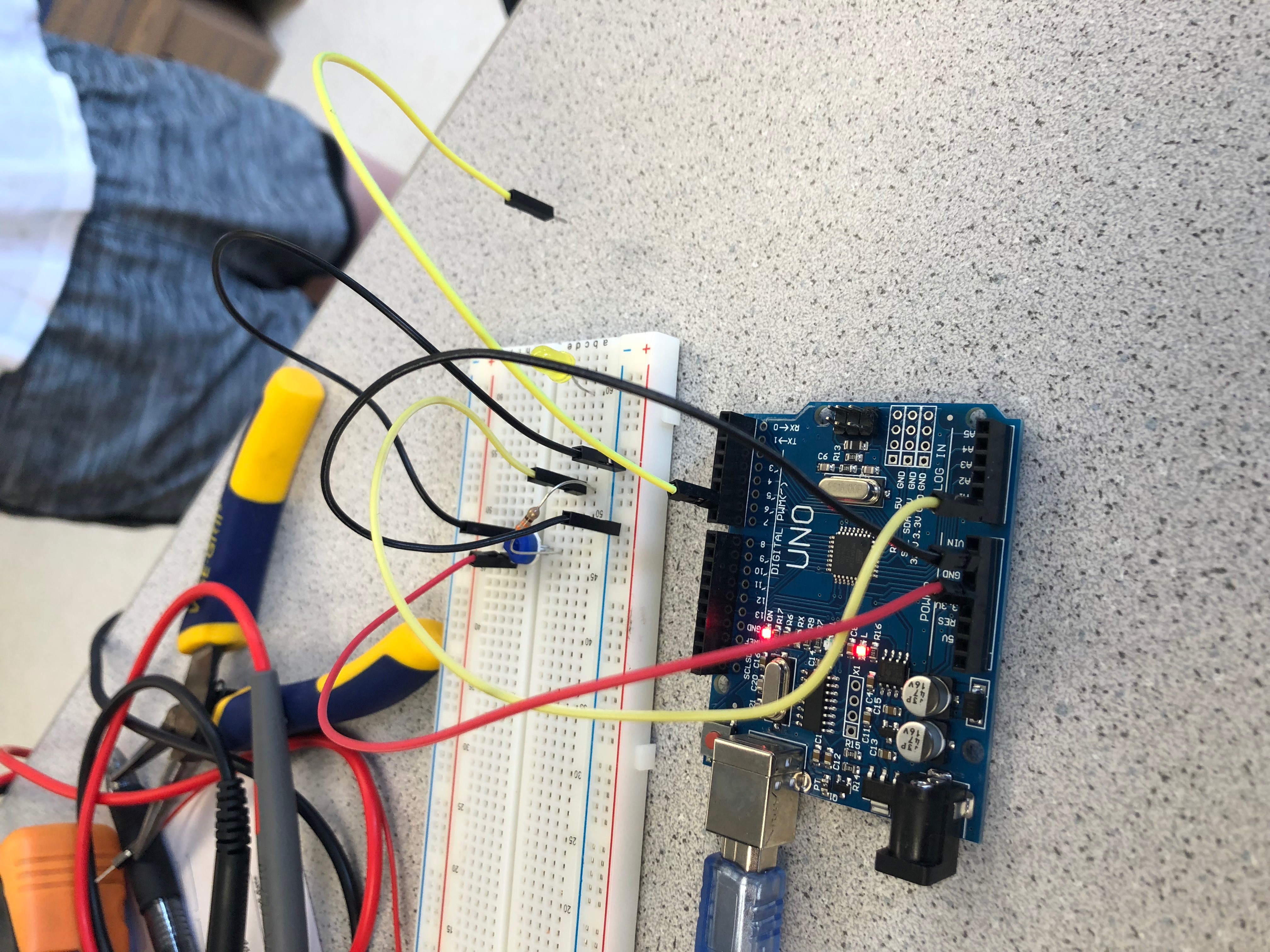
Next, we replaced the LED with a servo, and changed its speed using the potentiometer values. Unlike a typical servo where one can give values between 0 and 180 to correspond to a position, the parallax servo assigns different speeds based on the values it's given. For example, a value of 90 will stop the servo while the ranges 91-180 and 0-89 correspond to different speeds in opposite directions. Below is a short video to demonstrate!
Next, we assembled our robot using a chassis, two wheels along with their mounts, a ball bearing, and an arduino. Using the servo control we learned in the previous step, we set up the servo motion such that the robot would turn in a figure 8 motion.
        #include ;

        Servo parallax1;
        Servo parallax2;

        void setup() {
          parallax1.attach(6);
          parallax2.attach(5);
          }

        void loop() {
         parallax1.write(35);
         parallax2.write(94);
         delay(4000);
         parallax1.write(95);
         parallax2.write(165);
         delay(4000);
          }
See video below to observe!
When soldering:
We learned how to solder. Watch video below to see our experience with soldering.