| Component | Cost | Quantity |
|---|---|---|
| Ardino Uno | 16$ | 1 |
| Arduino Nano | 5$ | 1 |
| Line Sensor | 3$ | 3 |
| IR distance sensor | 7$ | 3 |
| Parallax Servos | 13$ | 2 |
| Camera | 14$ | 1 |
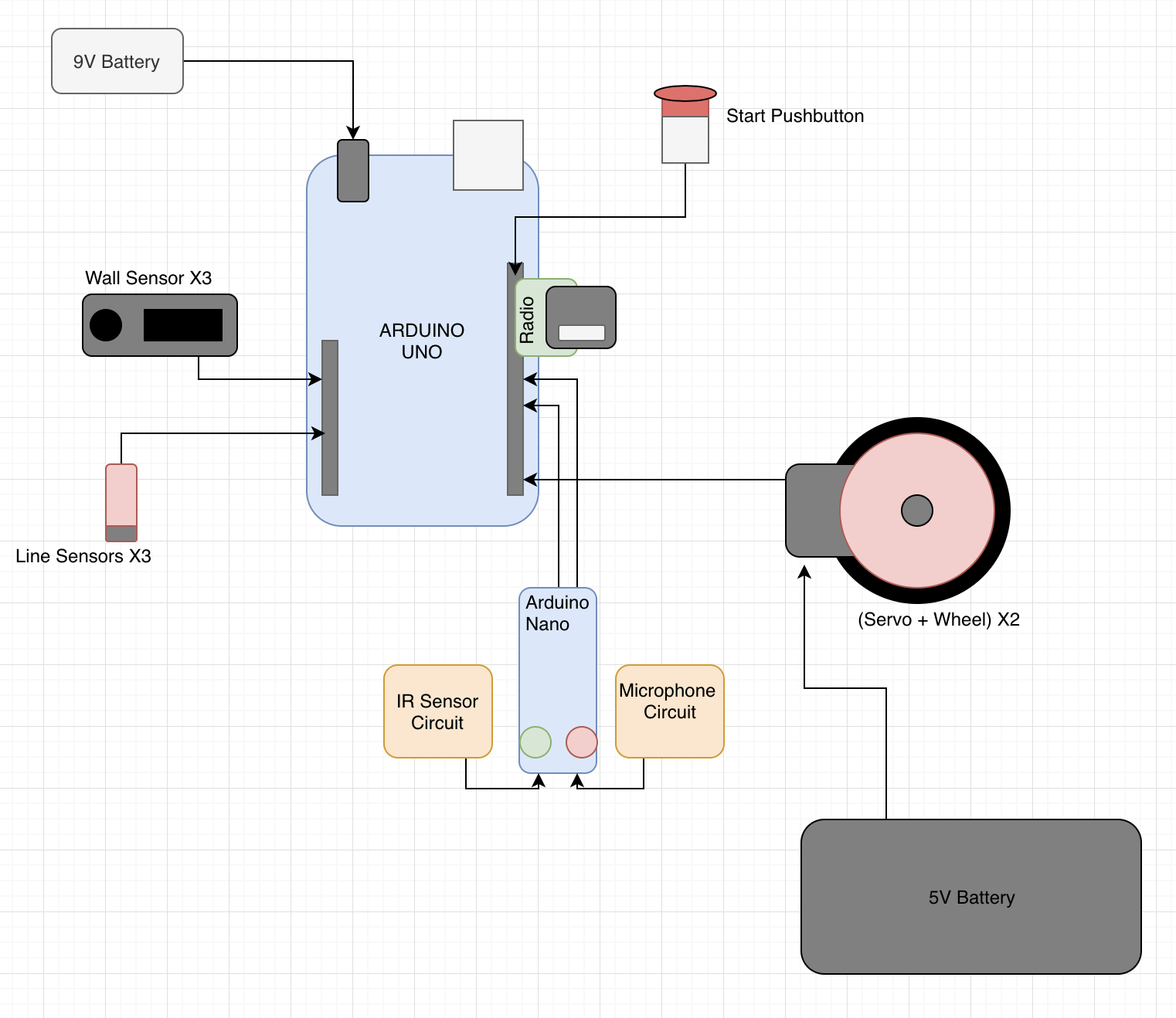
Our Arduino Uno pinout is as follows:
We decided to implement three line sensors. There are four possible scenarios given this configuration: when simply following a
straight line, we can either be perfectly on the line, in which case we simply continue going straight, or we can be veering left
or right slightly off the line, which is when the left or right sensor starts seeing white. To correct for this, we turn very slightly
back in the direction towards the line.
      int thresh=150;  //sets our threshold
      // correct for veer right
      while(analogRead(centSen)>thresh && analogRead(rightSen)>thresh && analogRead(leftSen)<thresh){
        parallax1.write(94);
        parallax2.write(75);
      }
      //correct for veer left
      while(analogRead(centSen)>thresh && analogRead(rightSen)<thresh && analogRead(leftSen)>thresh){
        parallax1.write(115);
        parallax2.write(94);
      }
      // go straight
      while(analogRead(centSen)<thresh && analogRead(leftSen)>thresh && analogRead(rightSen)>thresh){
        parallax1.write(100);
        parallax2.write(90);
      }
The fourth option is that we reach an intersection, in which case Gary launches a sequence of observations about his surroundings,
including wall detection and reporting information via radio about location and treasure detection.
We also decided to have three wall sensors. Initially we believed we should have a back wall sensor to detect if we started with a wall behind us, but given the general configuration of the maze we determined this to be unecessary. At each intersection, Gary checks the front, left and right wall sensors, by toggling a mux with the three analog inputs of the walls, and stores this information for both travel and maze mapping purposes.
bool frontw()
{
  set_select(0,1);
  int val = analogRead(sensor);
  if(val>frontwallThresh)return true;
  else return false;
}
bool leftw()
{
  set_select(0,0);
  int val = analogRead(sensor);
  if(val>sidewallThresh) return true;
  else return false;
}

bool rightw()
{
  set_select(1,1);
  int val = analogRead(sensor);
  if(val>sidewallThresh)  return true;
  else return false;
}
First, the optical team attempted to detect IR emitters on "hats" given to us by the TAs. The emit IR light at 6kHz, which is not visible to humans but can be read by our IR sensor (OP598). The IR sensor was hooked up as seen below.
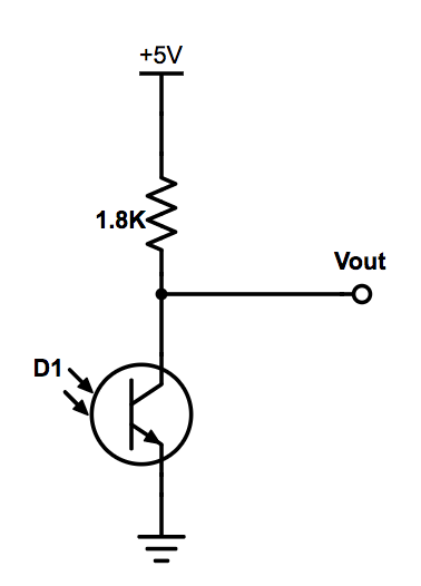
Fig.1: Image taken from 3400 website
We used the Arduino library Open Music Labs’ FFT to analyze all the input from the sensor, and tried to detect a peak at the desired frequency.
Next we implemented an amplifying circuit based on Team Alpha's solution from last year as recommended by the TAs after we could not get our personally designed op-amp circuit working.We used a similar circuit to the one below except we used a photo transistor in place of the microphone.
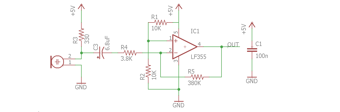
Fig.2: Image taken from Team Alpha's Website
After this we returned to the FFT library, where we were successfully able to identify the 6kHz bucket in the 42nd group, which the decoy hat had no affect on due to the spacing of the buckets. Below you can see our FFT analysis, where the 42nd bucket is clearly high in the presense of the hat and low without it.
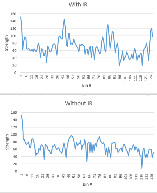
Fig.3: FFT of IR sensor
We began with the circuit provided for the lab (see IR) but realised that we needed to amplify our waveforms because they had been attenuated. We began the task of independently trying to build a circuit to detect our 660Hz sound wave. We worked hard switching between numerous designs of band-pass filters to amplifiers but nothing seemed to work for us. We decided to resort to Team Alpha's approach. We used the same circuit from the IR above. with slightly different values for the components. Our results, however, were very similar to Team Alpha's.
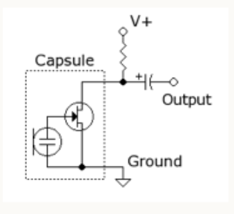
Fig. 4: Initial circuit built to test microphone. Image taken from 3400 website's Lab 2 instructions.
We run our circuit using the example fft arduino code (fft_adc_serial). We plotted our values on Excel.
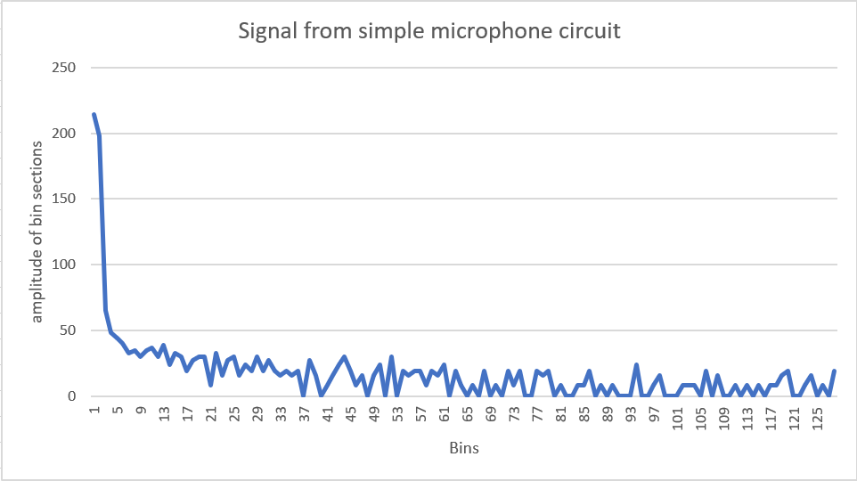
Fig. 5:Image of FFT of signal.
After adding the amplification, this was what we observed. We were able to locate our frequency in bin #5.
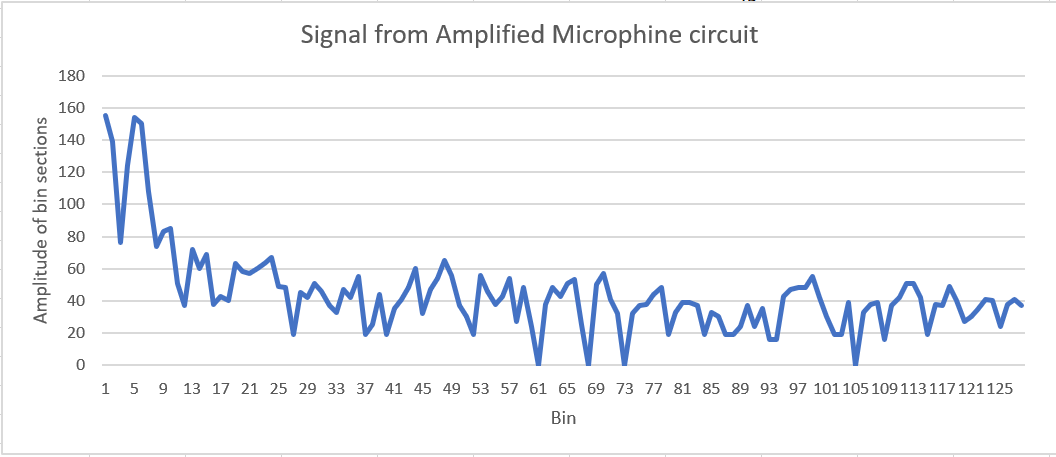
Fig. 6:Amplified version of fig. 5. 660Hz frequency is located in bin 5.
Although we initially were using spare parts from the lab, we ultimately decided to CAD our own chassis. Below is an image of the final CAD: the outside resembles a shell for our beloved Gary. The bottom shelf is for batteries, the next for our protoboard, the next for the arduino and FPGA, and the top for sensors, IR hat, and camera.
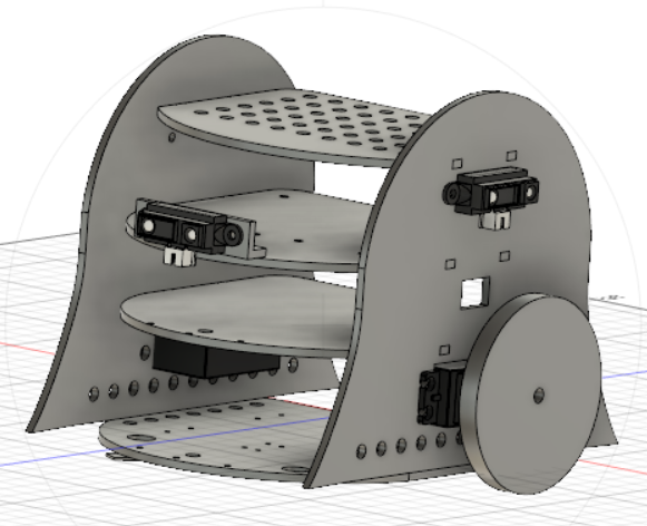
Final CAD of Gary
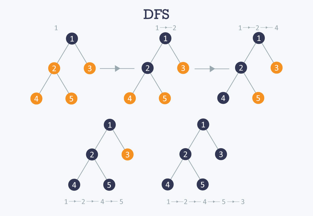
We chose DFS (depth first search) as our navigation algorithm, because this seemed to be the simplest to implement and we did not have a high collective knowledge of algorithms prior to the class. Depth First Search goes as far as it can down one side of a tree, in this case as far as we can go in one direction without looping to a node we've already visited or hitting a wall, and then returns to the last node that was split from and goes down the next branch as far as it can again. While this is not the most efficient, we've proven we can navigate several large mazes this way.
      //example for North facing; same applies for all other directions
      if      (dir_facing == North) {
        left_space[0]  = dataArray[0]-1;
        left_space[1]  = dataArray[1];
        right_space[0] = dataArray[0]+1;
        right_space[1] = dataArray[1];
        front_space[0] = dataArray[0];
        front_space[1] = dataArray[1]-1;
      }
      //example for left wall; same applies to front and right spaces.
     if (!leftw())  {
       if (totalSquares[left_space[0]-1][left_space[1]-1] == 0) {
        //Serial.println("can go left");
        visitStack.push (left_space[1]);
        visitStack.push (left_space[0]);
       }
      }
    int nextSquare[2] = {visitStack.pop(), visitStack.pop()}; //first choice is to move somewhere new

    //get deltas for direction to move in
    int deltaX = dataArray[0] - nextSquare[0];
    int deltaY = dataArray[1] - nextSquare[1];

    //check if the square is next door, and has been visited
    if (((abs(deltaX) + abs(deltaY)) != 1) || (totalSquares[nextSquare[0]-1] [nextSquare[1]-1] == 1)) {
      nextSquare[0] = history.pop(); //pop off history stack
      nextSquare[1] = history.pop();
    }
    else {
      //adding to the history so we can back track easily
      history.push (dataArray[1]);
      history.push (dataArray[0]);
    }
Once we have the deltaX/deltaY as shown above, we can choose which direction to move in based on the direction we're facing.
        //example of a time we would turn left; similar logic for going straight or turning right
      else if ((dir_facing == North && deltaX == 1) ||
               (dir_facing == East  && deltaY == 1) ||
               (dir_facing == South && deltaX == -1) ||
               (dir_facing == West  && deltaY == -1)) {
                turn_left();
               }
Below are a few videos where Gary navigates a few mazes using this algorithm!
Getting the camera to detect treasures was a long and tedious process but ultimately, we have something we are happy with. Here's how we got it to work.
The first thing we did was get the Arduinos programmed to write registers to the camera. To do this we read through the
camera datasheet and found the right registers to set the data structure (RGB444), resolution (176x144), camera noise, using an
external clock, pixel format and more. We had difficulty with getting the right results from our camera and the problem proofed to be
from the registers we had set using outdated data sheet. Eventually, we were able to get the correct registers and a snippet of our
code is shown below.
      	Serial.println("Writing registers");
    	Serial.println (OV7670_write_register(0x12, 0x80)); //COM7: Reset registers, enable color bar, resolution and pixel format
    	delay(100);
    	Serial.println(OV7670_write_register(0x12, 0x0E)); //COM7: Reset registers, enable color bar, resolution and pixel format
    	Serial.println(OV7670_write_register(0x0C, 0x08)); //COM3: Enable scaling
    	Serial.println(OV7670_write_register(0x14, 0x0B)); //COM9: To make the image less noisy
    	Serial.println(OV7670_write_register(0x11, 0xC0)); //CLKRC: Use external clock directly
    	Serial.println(OV7670_write_register(0x40, 0xD0)); //COM15: pixel format
    	Serial.println(OV7670_write_register(0x42, 0x08)); //COM17: DSP color bar enable (0x42, 0x08)
   	Serial.println(OV7670_write_register(0x1E, 0x30)); //MVFP: Vertically flip image enable
    	Serial.println(OV7670_write_register(0x8C, 0x02)); //enable RGB444
To run the Arduino program, we needed to protect the camera. We had to disable the internal pull-up resistors that are a part of
the Arduino’s I2C interface. This is because they pull the signals that set up our camera to 5V, while our camera requires 3.3V.
Sending 5V through will harm the camera. We did this by locating the twi.c file at C:\Program Files (x86)\Arduino\hardware\arduino\avr\libraries\Wire\src\utility.
Then we commented out the following lines of code:
       //activate internal pullups for twi
       digitalWrite(SDA,1);
       digitalWrite(SCL,1);
We read the camera data and the picture below shows the output. Comparing the output to the written values into the registers, we confirmed that our camera was working
correctly and is ready to send data into the DE0-Nano FPGA.
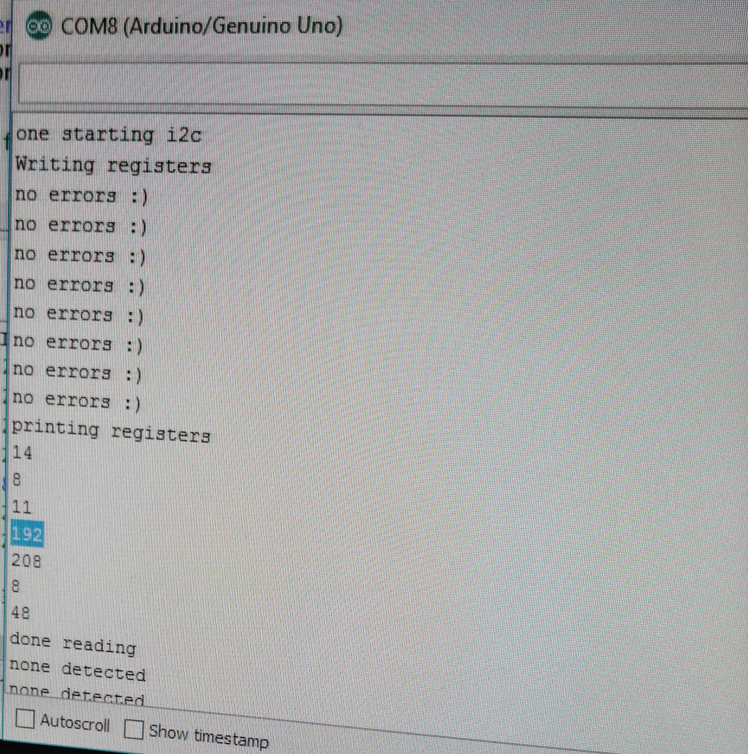
Fig.1: Camera Register Output
We tested our M9K block code which communicated with our VGA driver to output the colors which will be received from the camera. We wrote a few hard coded colors to be displayed on the monitor.
The following example shows how it is done
	    if(VGA_PIXEL_X>44 &&VGA_PIXEL_X<=66 &&VGA_PIXEL_Y<(`SCREEN_HEIGHT-1))begin
		pixel_data_RGB332 = 8'b11111100;  //set color
		W_EN = 1'b1;   //write enable
	    end
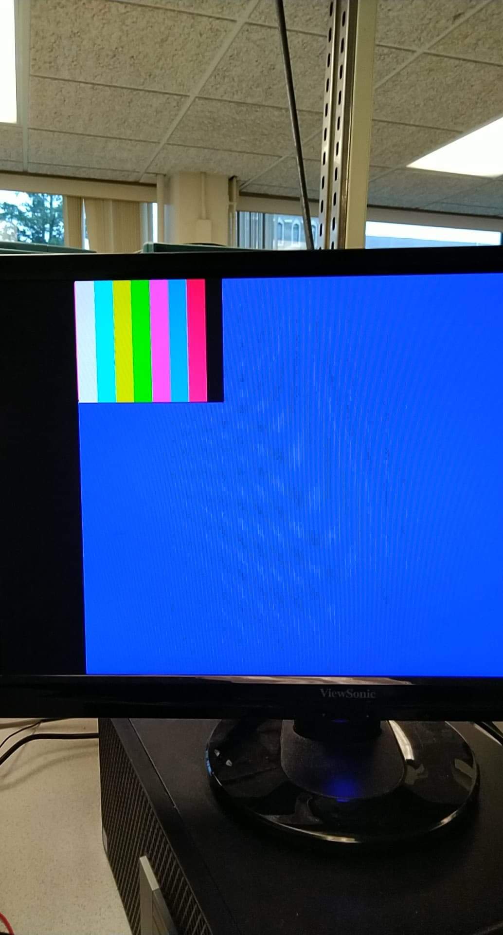
Fig.2: Color pattern output
Our camera outputs a data structure of RGB444 in 16 bits. We however need only 8 bits out of the 16 bits in order to save on memory. The Downsampling code collects all the data from the camera and selects only the most important bits necessary to display the colors we need. The OV7670 Camera can only output 8 bits of a pixel at a time through D7 - D0 (output connections). Using the camera clock cycle (see fig.3), we sampled down the output into RGB332.
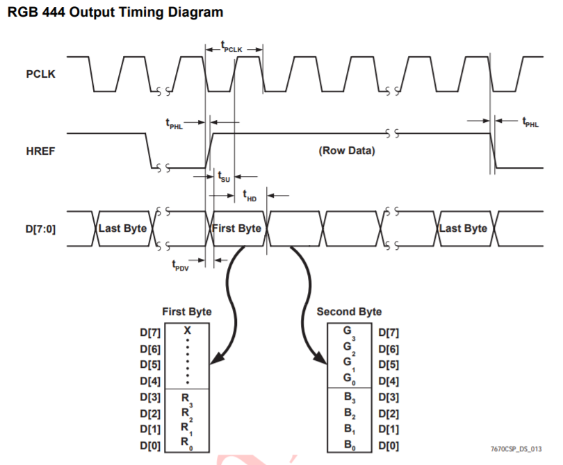
Fig.3: Clock cycle from the OV7670 Datasheet.This shows how the output from the clock is received based on time cycle
      //This set of codes receive camera data in RGB444 and downsamples it into RGB 332 by taking the important bits
      if (CAM_HREF_NEG) begin   //href clock is high
      	if (newByte == 1'b0) begin
				temp[7:0] = data;
				W_EN      = 1'b0;
				X_ADDR    = X_ADDR;
				newByte   = 1'b1;
				pixel_data_RGB332[4:0] = {data[7:5], data[3:2]};//get values for blue and green
			end
			else begin
				pixel_data_RGB332[7:5] = {data[3:1]};// get value for red
				X_ADDR = X_ADDR + 10'b1;
				W_EN = 1'b1;
				newByte = 1'b0;
			end
	end
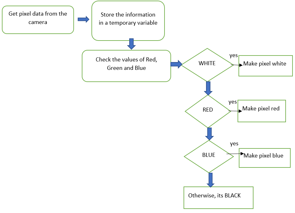
Fig.4: Making our colors look right
In order to determine whether there was actually a treasure as opposed to a few stray blue or red pixels, we used a threshold value. If the number of pixels of a certain color exceded this threshold, we assumed that there was a treasure and then began the shape detection process. Once done, we send the color and shape to the arduino, which displays this information on the serial monitor. If the threshold is not reached for either blue or red, "NULL" is sent to the ardunio. Below is a demonstration of this code.
Because of the code we used inside DEO_NANO to display color, detecting color was made simpler. Inside of DEO_NANO, whenever we saw a pixel that was above a certain threshold
of blue or red, we set that pixel to pure blue or red. In code, we set the pixels equal to 8'b000_000_11 and 8"b111_000_00. We are able to exploit this in our color detection.
Firstly, we only detect color if it is within a certain region we have specified. Inside of this region, we examine each pixel and determine whether it is red, blue, or neither.
If it is red or blue, we increment a variable that counts the amount of pixels of each color. Finally, if either count is above a specified threshold, we assume that one, we
seeing a treasure and two, that it is that color. If this criteria is not met, we display "NULL." An overview of the code used is shown below.
    	if(VGA_PIXEL_X>((`SCREEN_WIDTH/2)-30)&& VGA_PIXEL_X<((`SCREEN_WIDTH/2)+30) && VGA_PIXEL_Y<((`SCREEN_HEIGHT/2)+50)&& VGA_PIXEL_Y>((`SCREEN_HEIGHT/2)-50)) begin
		if(PIXEL_IN == BLUE) begin
			countBLUE = countBLUE + 10'd1;
		end
		else if(PIXEL_IN == RED) begin
			countRED = countRED +10'd1;
		end
	if(VGA_VSYNC_NEG == 1'b1 && lastsync == 1'b0) begin
		if(countRED >= R_CNT_THRESHOLD) begin
			begin red shape detection
		end
		else if(countBLUE >= B_CNT_THRESHOLD) begin
			begin blue shape detection
		end
		else begin
			display NULL
		end
We used a unique strategy to detect our shapes by counting pixels in segments of our figure. We first located the first pixel and last pixel in the image with the right color.
We use these to create three little sigments where we get the total number of color pixels. We then compare and average them to determine what shape the image has.
Below is a code snippet and a video to show the outcome.
         if(VGA_PIXEL_X>((`SCREEN_WIDTH/2)-30)&& VGA_PIXEL_X<((`SCREEN_WIDTH/2)+30) && VGA_PIXEL_Y<((`SCREEN_HEIGHT/2)+50)&& VGA_PIXEL_Y>((`SCREEN_HEIGHT/2)-50)) begin // only focus on a segment of the screen

		        if(PIXEL_IN == BLUE) begin     // this is for blue pixel. similar for red
			          countBLUE = countBLUE + 10'd1; // count blue
			          lastBLUE = VGA_PIXEL_Y;        // get last pixel
			          if(countBLUE==10'd1) firstBLUE= VGA_PIXEL_Y; // get first pixel
            end
            if(VGA_PIXEL_Y==firstRED+((lastRED-firstRED)*(1/3)) || VGA_PIXEL_Y ==((lastBLUE-firstBLUE)*(1/3)))begin  // at one third of the segment of whole shape
              blue1 = countBLUE; // take blue pixel count
              red1=countRED;     // or red pixel count
            end
            ... // take two more values for comparison
			// redi, for i = 1, 2... is a segment pixel count for segment i.
			if(red1<(red2-red1)&& (red2-red1)<(red3-red2)) begin  // analysis of segment pixels to determine shape
				RESULT = 3'b010; end         // triangle
			else if(red1<(red2-red1) && (red3-red2)<(red2-red1)) begin
				RESULT= 3'b001; end          // diamond
			else if((red1+red2)-(red2+red3)<= 10'd40 ||(red3+red2)-(red1+red2)<= 10'd40) RESULT = 3'b011; //Square
			//else RESULT = 3'b111;
At the end of the day, we couldn't quite get Gary to function to his full potential. In the competition, we were unable to implement our camera
or treasure detection due to lack of time and power, and we did not manage to start at the 660 hz frequency. Moreover, we could not detect other robots and often run into them during the competition.
Due to the issues we had with power, we ended up retuning our line sensing and wall following code, which turned out to be a big mistake, because in the maze
Gary often sensed walls that were not there or visa versa. Also, one of our wall sensors broke day-of, so we had to swap in a new one that
we did not get to test fully. Overall, it would have been nice to have a little more time to work on it in the end, but we know that we could
complete all the challenges had we had time to integrate.
If we are given the chance to do this again, we would give the sound and audio detection, and the camera their own voltage sources thereby reducing the work load on the main Arduino board.
We would also invest more time into integrating the codes as we added to the functions. Doing so at the last minute was not conducive and effective. We would also avoid changing our treshold for
sensors and other components we know worked well in the past. Our minor mistakes have been a lesson to us and given another project, we now know how best to handle it.
In all, this class was very challenging, yet very rewarding. Every time you managed to accomplish something, it immediately shot you down by not working the next time you powered up
your robot. Things didn't make sense. Sensors broke. Tears were shed. Friends were lost. Parts were stolen. Souls were crushed... Yet despite this constant heartbreak and stuggle and the countless weekends lost to Phillips 427, a whole
heck of a lot was learned in the making of Gary the robot. We learned that integration takes more time than getting independent parts working
in the first place, we learned that Arduinos are really bad at regulating power levels and that this ruins everything else,
and we learned how to make a pretty cool robot.